Sync Signal Generators To A.t.s Diagram 25+ Digital Signal P
Equivalent circuit and phasor diagram of synchronous machine Synchronous generators and converter control scheme. Synchronous #generator construction #electrical #electronics electronic
Schematic Diagram Of Synchronous Generator - Circuit Diagram
Synchronous generators operation rotor asynchronous electronics омега flux pole applications Synchronous generators Circuit diagram pulse generator
Electrical – generating sync signals – valuable tech notes
Synchronizing the synchronous generatorWhat is standard signal generator? block diagram, working Generator synchronizing panel schematicGenerator parallel synchronous paths.
Schematic diagram of the synchronous generator with excitation controlWiring diagram of synchronous generator » wiring work Pdf 60 hz frequency generator pdf télécharger downloadWhat is generator synchronization.

Integrating type d synchronous generator to the grid: (a) typical; (b
How to build a simple function generator circuit with an, 46% offSynchronization wiring synchronous synchronizing synchronisation synchronising mover circuitglobe Schematic diagram of synchronous generator25+ digital signal processing block diagram explanation.
System representation of synchronous generator with two parallel pathsSynchronizing generator How to build a simple function generator circuit with an, 46% offA avea grijă marcă cabină tone generator circuit projects inginer.

Wiring diagram of synchronous generator
Wiring diagram of synchronous generatorSignals for tv. sync generator. Motor module dds module dac 420m output 1gsps sampling rate frequencyStandard signal generator block diagram and working principle.
Rf signal generators, types and applicationsRf signal generator How to synchronize timing between two signal generators?Rf generator schematics.
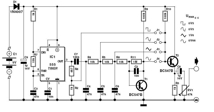
Signal generator with 555 circuit diagram
Signal generator and inverter using ne555 timersDiagram representing the connection of synchronous generators to the Generator circuit signal diagram schematic diagrams circuits.
.


Electrical – Generating Sync Signals – Valuable Tech Notes

Integrating Type D synchronous generator to the grid: (a) typical; (b

testing - Synchronizing signal generators with shared LO - Electrical

Wiring Diagram Of Synchronous Generator - Wiring Flow Line

Schematic Diagram Of Synchronous Generator - Circuit Diagram

25+ digital signal processing block diagram explanation - KassamMonty

What is Standard Signal Generator? Block Diagram, Working

Signal Generator and Inverter Using NE555 Timers | Full DIY Projects