System Verilog Design Diagram Digital System Design: Verilog
Design a digital system with verilog that implements System verilog based generic verification methodology for ips/asics Solved you must build a system verilog module and its
Verilog Code For 4 To 16 Decoder Using 2 To 4 Decoder - Printable Online
System verilog for design study notes Digital system design verilog hdl design at structural Solved design a verilog model that describes the following
System design through verilog lect15
Digital design using system verilog (video course)Digital system design: verilog hdl basic concepts (pdf) digital system design verilog: system tasks and …jufiles.com/wpDigital system design using verilog unit-5.
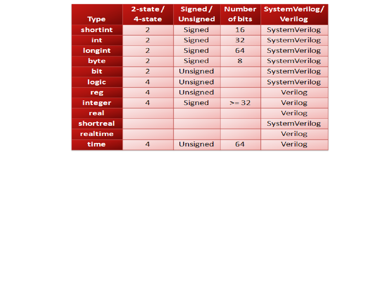
Verilog system systemverilog sva assertions example verification types functional bus model usage guidelines advantages important electronicsmakerVerilog types system systemverilog state Verification methodology verilog diagram ips systemverilog specification socs asics dutSystem verilog testband for parallel to serial converter.

(pdf) digital systems design with system verilog
System verilog for design a guide to using systemverilog for hardwareLec 19: digital system design using verilog Systemverilog testbench/verification environment architectureMicrocontroller verilog cpu multiplication vhdl datapath fsm assembly fixed lưu processor đã từ.
Digital system design verilog hdl design at structuralVerilog code for microcontroller, verilog implementation of a [solved] given the following system verilog description, draw aArchitecture diagram examples.
![[Solved] Given the following System Verilog description, draw a](https://i2.wp.com/www.coursehero.com/qa/attachment/38994191/)
Systemverilog testbench example 01
Circuit diagram to structural verilogSystem verilog for design System verilog assertions (sva)Digital system design verilog hdl 2005 verilog hdl.
System verilogSystem verilog for digital design ~ vuongbkdn System design through verilog lecture13Digital system design using verilog.
Testbench systemverilog sv example tb verification
Digital system design using verilog : module 5Testbench verification systemverilog uvm maven silicon follows Digital system design using verilogVerilog code for 4 to 16 decoder using 2 to 4 decoder.
Verilog hdl methodologiesElectrical – how to create verilog or vhdl from a quartus design .


System Verilog Assertions (SVA) - Types, Usage, Advantages and

Digital System Design Using Verilog | Introduction #verilog #gate #

(PDF) Digital System Design Verilog: System Tasks and …jufiles.com/wp

System verilog testband for parallel to serial converter - cloudoperf

Verilog Code For 4 To 16 Decoder Using 2 To 4 Decoder - Printable Online

Design a digital system with Verilog that implements | Chegg.com

(PDF) Digital Systems Design with System Verilog - DOKUMEN.TIPS

Electrical – How to create Verilog or VHDL from a Quartus design